
At first glance, aluminum casting appears straightforward.
Aluminum is melted, introduced into a mold, allowed to solidify and removed as a finished shape.
But an industrial aluminum component is rarely that simple.
Behind every reliable casting lies a sequence of engineering decisions involving component geometry, alloy selection, casting method, tooling, metal quality, solidification, machining, surface treatment and dimensional verification.
For an OEM, the real objective is not simply to produce a casting.
It is to manufacture a component that performs its intended function repeatedly, fits correctly into the final assembly and meets the requirements defined on the technical drawing.
That distinction changes everything.
A precision aluminum component does not begin with molten metal.
It begins with engineering requirements.
A Precision Component Begins Before the Metal Is Melted
In our previous Journal article, we explored how aluminum evolved from a precious metal into one of modern industry's most important engineering materials.
Modern aluminum casting represents the next chapter of that evolution.
Before a furnace is heated or a mold is filled, engineers must understand what the component is expected to do.
Is it a structural housing?
Does it contain bearing seats or precision bores?
Will it operate outdoors?
Must it dissipate heat?
Will another component seal against one of its surfaces?
Does it require threads, mounting interfaces or tightly controlled datum surfaces?
Will production involve hundreds of components or hundreds of thousands?
These questions influence almost every manufacturing decision that follows.
The geometry visible on a technical drawing is therefore only one part of the manufacturing requirement. Tolerances, material specifications, annual volumes, surface requirements, mechanical performance and assembly conditions must also be considered.
This early evaluation is often described as Design for Manufacturing, or DFM.
The objective is not necessarily to change the customer's design. It is to understand how that design can be manufactured reliably and, where appropriate, identify features that may influence tooling complexity, casting quality, machining requirements or production cost.
Step 1: Understanding the Technical Drawing
For drawing-based OEM manufacturing, the technical drawing is one of the most important links between design engineering and production.
It defines far more than the external shape of a component.
Depending on the application, it may specify:
dimensional tolerances,
geometric tolerances,
datum references,
material or alloy requirements,
surface roughness,
threaded features,
machining requirements,
coating or finishing specifications,
inspection requirements,
and other critical characteristics.
Not every dimension requires the same manufacturing strategy.
A cast external profile may tolerate the dimensional variation inherent to the selected casting process, while a bearing bore, sealing surface or precision mounting interface may require subsequent CNC machining.
Recognizing this distinction is fundamental.
One of the key engineering decisions is determining which features should remain as-cast and which should be machined.
Machining everything unnecessarily increases production time, material removal and cost.
Trying to cast every critical feature to final precision can create a different problem: the selected casting process may simply not be capable of consistently maintaining the required tolerance.
Good process planning finds the correct balance between the two.
Step 2: Selecting the Right Aluminum Casting Process
There is no single aluminum casting process suitable for every component.
The appropriate method depends on geometry, component size, production volume, required surface quality, dimensional expectations, tooling economics and mechanical requirements.
Three important industrial routes are:
Sand Casting
Sand casting provides substantial design flexibility and is particularly useful for larger components, complex geometries and low-to-medium production volumes. Tooling investment can often be lower than permanent-tool processes, although surface finish and dimensional repeatability generally differ from die-based casting methods.
Gravity Die Casting / Permanent Mold Casting
In gravity casting, molten aluminum fills a reusable metallic mold primarily under the influence of gravity. The process can provide good repeatability, surface quality and mechanical properties and is widely applicable to medium-volume industrial components.
High-Pressure Die Casting
High-pressure die casting injects molten metal into a steel die at high speed and pressure. It is particularly effective for complex, relatively thin-walled components manufactured at high production volumes and can provide excellent repeatability and productivity.
Choosing between these processes is not simply a question of asking which technology is “best.”
The correct question is:
Which process is best for this component, at this production volume, with these technical requirements?
That subject deserves deeper examination, and we will address it separately in the next stage of this Journal series.
Step 3: Choosing the Aluminum Alloy
Selecting the casting process is only part of the engineering decision.
The aluminum alloy itself also matters.
Different casting alloys provide different combinations of:
castability,
mechanical strength,
ductility,
corrosion resistance,
thermal conductivity,
machinability,
dimensional stability,
and response to heat treatment.
An alloy suitable for a high-volume die-cast housing may not be the ideal choice for a gravity-cast structural component.
Similarly, an outdoor component exposed to moisture and changing environmental conditions may prioritize corrosion behavior differently from an internal machinery component.
The alloy must therefore be considered together with the component's function and manufacturing route.
This is an important principle in aluminum manufacturing:
Material selection and process selection should not be treated as independent decisions.
The geometry, application, casting method, machining operations and expected performance of the finished component all interact.
Step 4: Tooling and Mold Preparation
Once the component and process have been defined, attention turns to tooling.
The mold does much more than reproduce the external geometry of the part.
Its design influences how molten metal enters the cavity, how air can escape, how the component solidifies and how the finished casting can be removed.
Depending on the casting method, engineers may need to consider elements such as:
parting lines,
draft angles,
cores,
gates and runners,
vents,
ejector locations,
shrinkage allowances,
machining allowances,
and thermal behavior within the mold.
These details may be invisible in the finished component, but they can have a major influence on manufacturing stability.
For example, draft is a slight angle applied to certain surfaces to allow a casting to be removed from its mold more reliably.
A parting line is the interface where sections of the mold meet.
A machining allowance is intentional additional material placed on selected areas of the casting so that those surfaces can later be CNC machined to their final dimensions.
These are small details from the customer's perspective, but they are fundamental elements of casting engineering.
Step 5: Melting and Molten Metal Control
Only after these engineering decisions have been made does the process reach the stage most people associate with casting:
melting the aluminum.
But even here, simply reaching the melting temperature is not enough.
Molten metal quality has a direct relationship with casting quality.
Temperature must be controlled according to the alloy and process. Excessive temperatures can increase oxidation and influence metal quality, while insufficient temperature can affect mold filling.
Hydrogen is another important consideration in molten aluminum.
Liquid aluminum can dissolve significantly more hydrogen than solid aluminum. As the metal solidifies, excess hydrogen may contribute to gas porosity if melt quality is not adequately controlled.
Oxide films and inclusions can also influence casting integrity.
For this reason, industrial melt preparation may involve controlled practices such as degassing, fluxing, filtration or other treatment methods depending on the alloy, casting process and quality requirements.
The objective is not merely to create liquid aluminum.
It is to deliver controlled molten metal to a controlled casting process.
Step 6: Casting and Solidification
The molten aluminum now enters the mold and begins transforming from liquid metal into a solid component.
This transition is one of the most critical stages of the entire process.
Metal must reach the necessary regions of the cavity before solidification prevents further flow.
At the same time, engineers must consider how different sections of the component cool.
Thick sections generally solidify differently from thin sections.
Abrupt changes in wall thickness can create localized thermal differences.
Poor feeding or uncontrolled solidification can contribute to shrinkage-related defects.
Gas entrapment, oxide formation and turbulent metal flow can introduce additional challenges depending on the casting method.
This is why modern casting engineering pays close attention not only to how the mold fills, but also to how the casting solidifies.
Simulation technology can help predict metal flow, temperature distribution, air entrapment and solidification behavior before production tooling is finalized.
The objective is increasingly to solve potential manufacturing problems digitally rather than discovering them after thousands of components have entered production.
Step 7: CNC Machining — Where Precision Takes Over
A casting can reproduce highly complex geometry, but many industrial components contain functional features requiring greater dimensional precision than the casting process alone is intended to provide.
This is where CNC machining enters the manufacturing chain.
Typical machined features can include:
bearing bores,
threaded holes,
sealing faces,
mounting surfaces,
precision pockets,
datum surfaces,
shaft interfaces,
and other critical geometries.
The casting therefore acts as a near-net-shape manufacturing process.
It creates a component already close to its final geometry, reducing the amount of material that must subsequently be removed.
CNC machining then concentrates precision where precision is actually required.
This combination can be highly efficient.
Instead of machining an entire complex component from a large solid block of aluminum, casting can establish most of the geometry first. Machining is then applied strategically to the functional interfaces.
However, casting and machining cannot be planned independently.
The casting must provide sufficient machining allowance.
Fixturing points must be considered.
Datum strategies must be established.
Potential casting variation must be understood so that machining consistently locates the component correctly.
The best results therefore come when casting engineering and machining engineering are considered as parts of the same manufacturing system.
Step 8: Surface Finishing
Once dimensional machining is complete, the component may require additional surface treatment.
The appropriate finishing process depends entirely on its function and environment.
Possible treatments include:
powder coating,
painting,
anodizing where alloy and application permit,
shot blasting,
vibratory finishing,
polishing,
or other customer-specified treatments.
For outdoor components, surface finishing may form part of the corrosion-protection strategy.
For visible products, appearance may be equally important.
For machinery components, the priority may instead be surface cleanliness, protection or compatibility with the final assembly.
Surface treatment should therefore not be viewed simply as a cosmetic final operation.
In many applications, it is an engineering requirement of the finished component.
Step 9: Quality Control and Dimensional Verification
The final question is simple:
Did the manufacturing process produce what the drawing requires?
Quality control provides the answer.
Inspection requirements depend on the component and its application, but may include dimensional measurement, material verification, surface inspection and process-specific testing.
Critical dimensions can be checked using conventional measuring equipment or coordinate measuring machines depending on geometry and tolerance requirements.
Material composition can be verified where required.
Surface characteristics can be inspected against customer specifications.
For certain applications, additional testing may be necessary depending on functional requirements.
Modern quality planning also distinguishes between ordinary dimensions and Critical-to-Quality characteristics — CTQs.
A component may contain dozens of dimensions, but only a smaller number may directly influence sealing, alignment, safety, assembly or performance.
Identifying these characteristics allows inspection resources to focus on the features that matter most to the final product.
Quality, therefore, is not simply an inspection activity performed at the end of production.
It begins with understanding the drawing and continues throughout the manufacturing process.
From Drawing to Finished OEM Component
The complete journey can now be seen clearly:
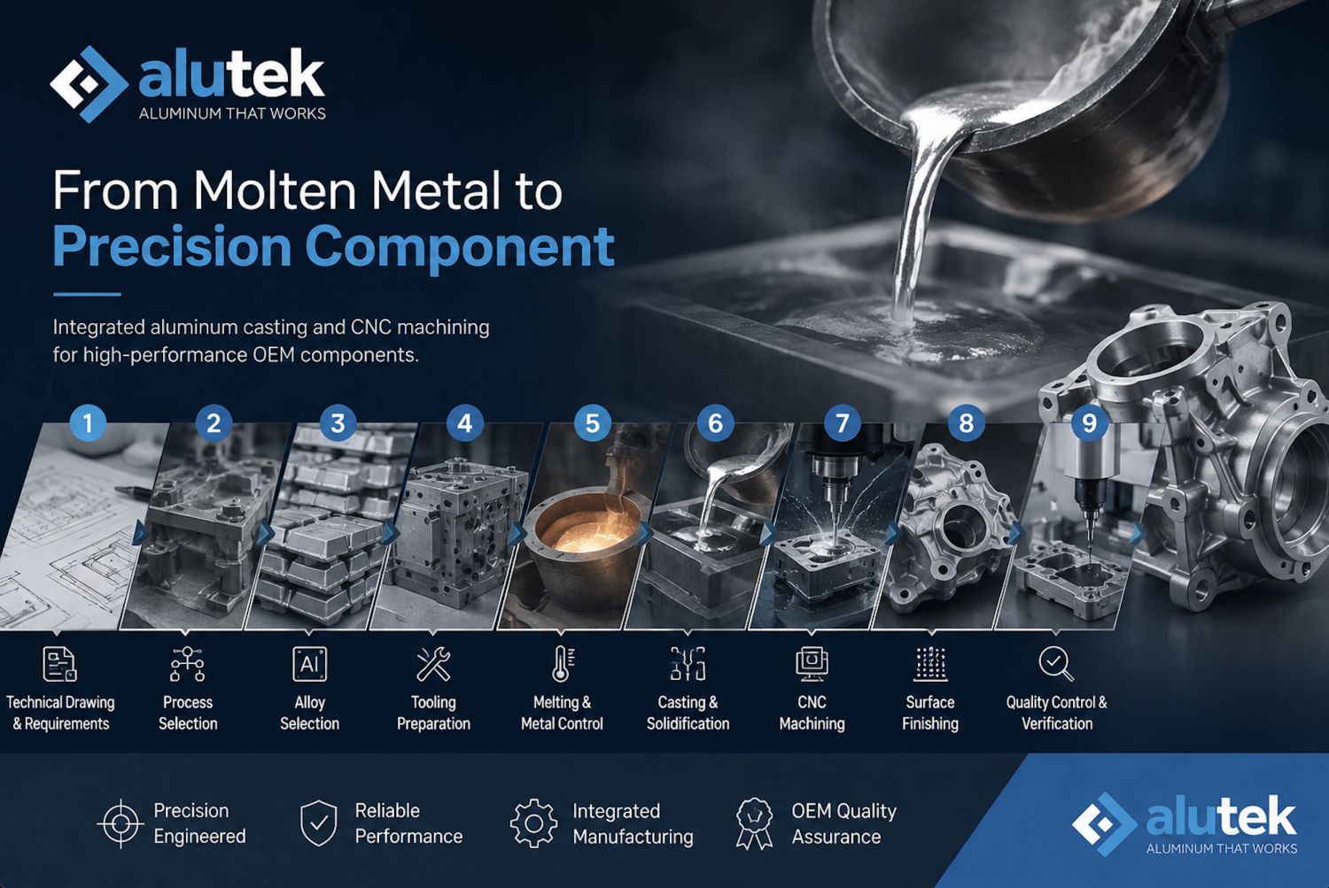
Technical Drawing → Process Engineering → Alloy Selection → Tooling → Melting → Casting → CNC Machining → Surface Finishing → Quality Control → Finished OEM Component
Molten aluminum is only one stage in this sequence.
What ultimately determines the quality of the finished component is the interaction between every stage.
A well-designed mold cannot compensate for uncontrolled molten metal.
Excellent casting cannot compensate for an incorrect machining datum.
Precision machining cannot correct every fundamental casting defect.
And final inspection cannot manufacture quality into a component after the process has already failed.
Reliable production therefore depends on something broader:
process integration.
For OEM manufacturers, this is increasingly important because the component entering the assembly line is rarely “just a casting.”
It is an engineered product with defined material properties, dimensions, interfaces, surfaces and functional requirements.
At Alutekworks, our approach to drawing-based OEM manufacturing reflects this integrated process: combining aluminum casting, CNC machining, surface finishing and quality control according to customer drawings and technical requirements.
Because the real transformation in aluminum casting is not simply:
liquid metal → solid metal.
It is:
engineering requirement → controlled process → precision component.